Availability: In stock
Couldn't load pickup availability
Free shipping and returns available on all orders!
We ship all orders within 5-10 business days
We advise routinely dusting your items with a gentle cleanser to preserve its look. Periodically, it may need to be softly wet with a mild detergent solution.


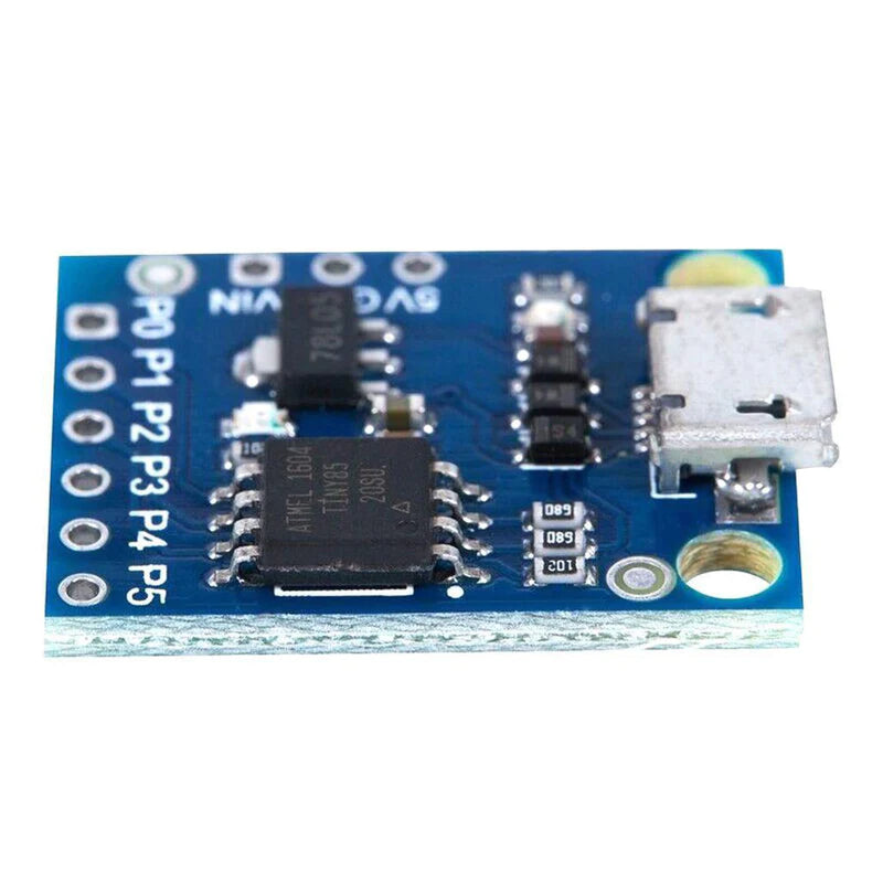
If you want to embed a microcontroller into a project and are looking for something smaller and cheaper than an Arduino and you don’t need a lot of I/O pins or code space, the ATtiny85 can be a good solution.
Pin Configuration
| Power | The module can be powered off the USB connector as with any Arduino boards that have USB connectors. |
| USB Interface | The module uses pins 3 & 4 for USB communications. |
| I2C Interface | The I2C interface is connected to pin 0 (SDA) and pin 2 (SCL). |
| SPI Interface | The SPI interface is connected to pin 0 (MOSI), pin 1 (MISO), and pin 2 (SCK). |
| Digital I/O | Pins 0,1,2,3,4,5 are capable of digital I/O. |
| Analog Outputs | Pins 0 & 1 PWM operates at 504Hz while pin 4 operates at a higher 1007Hz. |
| Analog Inputs | The ATtiny85 has a built-in 10-bit ADC and can read Analog voltages on 4 of the pins. |
Features
Specification
| Microcontroller | Atmel ATtiny85 |
| 5V Input Operating Voltage Range | 3 – 5.5 V |
| VIN Input Voltage (recommended) | 7-12 V |
| Digital I/O Pins | 6 |
| PWM I/O Pins (Shared with Digital I/O) | 3 |
| Analog Input Pins (Shared with Digital I/O) | 4 |
| DC Current per I/O Pin | 20 mA |
| Flash Memory | 8 KBytes |
| SRAM | 512 Bytes |
| EEPROM | 512 Bytes |
| Clock Speed | 16.5 MHz |
| Power Consumption (Max for Package) | 200 mA |
| Built-in LED | Attached to digital I/O Pin 1 |
| USB Connector Style | Micro-B Female |


